What to do When Your Hydraulic System is Contaminated

There are generally only two conditions that necessitate changing the oil in a hydraulic system: 

1. Base oil degradation 

2. Additive depletion

Contaminants of the hydraulic fluid such as hard and soft particles and water can be removed from the oil, and therefore, don’t mandate an oil change. 

Techniques for flushing hydraulic systems vary in cost and complexity. Before I discuss some of these methods, let’s first distinguish between flushing the fluid and flushing the system.

The objective of flushing the OIL is to eliminate contaminants such as particles and water. 

This is usually accomplished using a filter cart or by diverting system flow through an external fluid-conditioning rig. 

The objective of flushing the SYSTEM is to eliminate sludge, varnish, debris and contaminated or degraded fluid from conductor walls and other internal surfaces, and system dead spots.

Reasons for performing a SYSTEM flush include: 

  1. Fluid degradation – resulting in sludge, varnish or microbial deposits. 
  2. Major failure – combined with filter overload disperses debris throughout the system. 
  3. New or overhauled equipment – to purge ‘built-in’ debris.
Common methods for flushing hydraulic systems include:
 
* Double oil and filter change.
* Mechanical cleaning.
* Power flushing.
 
The technique or combination of techniques employed will depend on the type of system and its size, your reliability objectives for the equipment and the reason for the flush.

Double oil and filter change 

This technique involves an initial oil drain and filter change, which expels a large percentage of contaminants and degraded fluid. The system is then filled to the minimum level required and the fluid circulated until operating temperature is reached and the fluid has been turned over at least five times. 

The oil is drained and the filters changed a second time. An appropriate oil analysis test should be performed to determine the success of the flush.

To maximize the effectiveness of this technique, the system should be drained as thoroughly as possible and the reservoir mechanically cleaned.

Mechanical cleaning 

Although not technically a flushing technique, the selective use of mechanical cleaning may be incorporated in the flushing strategy. 

This can involve the use of a pneumatic projectile gun to clean pipes, tubes and hoses, and disassembly of the reservoir and other components for cleaning using brushes and solvents.

Mechanical cleaning is labor intensive and, therefore, costly. It carries with it reliability risks associated with opening the hydraulic system and intervention by ‘human agents’.

Power flushing 

Power flushing involves the use of a purpose-built rig to circulate a low viscosity fluid at high velocities to create turbulent flow conditions (Reynolds number > 2000). 

The flushing rig is typically equipped with a pump that has a flow rate several times that of system’s normal flow, directional valves, accumulators, fluid heater and chiller and of course, a bank of filters. 

The directional valves enable the flushing direction to be changed, the accumulators enable pulsating flow conditions and the heater and chiller enable the fluid temperature to be increased or decreased, all of which can assist in the dislodgment of contaminants. 

Analysis of the flushing fluid is performed regularly during the flushing operation to determine the point at which the system has been satisfactorily cleaned. 

What about components? 

The question of how to deal with system components arises when contemplating a hydraulic system flush. Plumbing should be flushed first in isolation from pumps, valves and actuators. Once the conductors have been flushed clean, valves and actuators can be gradually included in the flushing circuit.

The decision to disassemble and mechanically clean components will depend on the type of equipment, your reliability objectives and the reason for the flush.


Craig Cook 

A single pressure spike in a fraction of a second is all this takes…

When a hydraulic system sees a spike in pressure it won’t necessarily blow up with a bang. But damage can occur in a number of ways. 

In fact, a single pressure spike of sufficient magnitude can render a piston pump or motor unserviceable.

Here’s how:

In axial and bent axis piston pump and motor designs, the cylinder barrel is hydro-statically loaded against the valve plate.

To maintain full-film lubrication between the rotating cylinder barrel and the stationary valve plate, the hydro static force holding them in contact is offset by a hydro-static force acting to separate the parts.

The higher the operating pressure, the higher the hydro-static force holding the cylinder barrel in contact with the valve plate.

However, if operating pressure exceeds design limits, the cylinder barrel will separate from the valve plate.

Design geometry prevents a perfect alignment of the opposing hydro-static forces. This misalignment creates a twisting force (torque) on the cylinder barrel.

During normal operation, this torque is supported by the drive shaft – in axial piston designs or center pin in bent axis designs.

If operating pressure exceeds design limits, the magnitude of the torque created causes elastic deformation of the drive shaft or center pin. This allows the cylinder barrel to separate from the valve plate.

Once separation occurs, the lubricating oil film is lost and the resulting two-body abrasion damages (scores) the sliding surfaces of the cylinder barrel and valve plate.

Erosion of the kidney area of the valve plate can also occur as high-pressure fluid escapes into the case at high velocity. This surge of flow into the case can cause excessive case pressure, resulting in shaft seal failure.

Craig Cook

Hot to Locate Abnormal Heat Load

Overheating problems can come from two areas: 

The cooling circuit or the hydraulic system.

If the indications are that the cooling circuit is functioning satisfactorily but the system is overheating – then we need to locate the source of the ‘abnormal’ heat load.

When fluid moves from a high pressure zone to a low pressure zone we call this pressure drop.

When a pressure drop occurs WITHOUT useful work, heat is generated. For example, the pressure drop across the ports of a properly functioning motor produces torque at the motor’s drive shaft and ultimately useful work.

On the other hand, the pressure drop across a relief valve doesn’t produce any work, so this energy is converted to heat – which is an undesirable heat load on the system.

Because a pressure drop without useful work creates heat, an infra-red thermometer can often be used as a quick and effective means of locating abnormal heat load.

For example, if oil is passing over a relief valve, the localized heat generation means this component will be hotter than the rest of the system.

Craig Cook

How Hot is Too Hot?

When it comes to the oil’s operating temperature – how hot is too hot?

Heating of hydraulic fluid in operations is caused by inefficiencies. Inefficiencies result in losses of input power, which are converted to heat.

A hydraulic system’s heat load is equal to the total power lost (PL) through inefficiencies
and can be expressed as:

PLtotal = PLpump + PLvalves + PLplumbing + PLactuators

If the total input power lost to heat is greater than the heat dissipated, the hydraulic system will eventually overheat.

Hydraulic fluid temperatures above 180F (82C) damage most seal compounds and accelerate degradation of the oil.

So while the operation of any hydraulic system at temperatures above 180F (82C) should be avoided, fluid temperature is too high when viscosity falls below the optimum value for the hydraulic system’s components.

This can occur well below 180F (82C), depending on the fluid’s viscosity grade (weight).

To achieve stable fluid temperature, a hydraulic system’s capacity to dissipate heat must exceed its inherent heat load.

For example, a system with continuous input power of 100 kW and an efficiency of 80% needs to be capable of dissipating a heat load of at least 20 kW.

It’s important to note that an increase in heat load or a reduction in a hydraulic system’s capacity to dissipate heat will alter the balance between heat load and dissipation.

As you’ve probably gathered, there are only two ways to solve overheating problems in hydraulic systems:

1. Decrease heat load; or
2. Increase heat dissipation.

Decreasing heat load is always the preferred option because doing so increases the efficiency of the hydraulic system.


Craig Cook

Tips for Choosing the Right Hydraulic Hose

When choosing a hydraulic hose you should pay close attention to the following characteristics:

  • Working Pressure – Choose a hose that is suitable for the working pressure of the machine
  • Wire or Sheathing – Install wire or sheathing when fabricated if the hose will be used in an area exposed to damage from pinching or crushing
  • Fluid – Make sure you use a hose compatible with the fluids that are used in the machine
  • Size/Inner Diameter – Choosing the right size hose is important in order to avoid unwanted friction. When fluid rubs against the inner surface of the hose, friction is created, which creates heat, back pressure increases, and the rate of flow is reduced
  • Match the Fluid Viscosity to the Operating Temperature – In order to achieve maximum component life, the fluid’s viscosity grade should be correctly matched to the operating temperature range of the hydraulic system


Craig Cook

Three Common Causes of Hydraulic Cylinder Failure

Here are three common causes of hydraulic cylinder failure: 

Ballooned Tubes 

Ballooning of the cylinder tube is usually caused by excessive honing or insufficient wall thickness and/or material strength for the cylinder’s operating pressure. 

Once the tube balloons, the correct tolerance between the piston seal and tube wall is lost, and high-pressure fluid bypasses the seal. This high velocity fluid can erode the seal and localized heating caused by the pressure drop across the piston reduces seal life. 

Insufficient Bearing Area 

If the internal bearing areas in the gland and on the piston are insufficient to carry the torsional load transferred to the cylinder, excessive load is placed on the rod and piston seals. This results in deformation and ultimately premature failure of the seals. 

Rod Finish 

The surface finish of the cylinder rod can have a dramatic effect on the life of the rod seal. If the surface roughness is too low seal life can be reduced through inadequate lubrication. 

If the surface roughness is too high, contaminant ingression is increased and an unacceptable level of leakage can result. 

Keep in mind that not all hydraulic cylinders are made equal. So if you have hydraulic cylinders that suffer recurring failure, it’s likely that modifications to the cylinder are required to break the vicious circle of failure and repair.

Craig Cook


Is it Time for a Pump Overhaul?

How to determine the condition of the hardest working component of a hydraulic system – the pump

As a pump wears in service, internal leakage increases and therefore the percentage of flow available to do useful work (volumetric efficiency) decreases. 

If volumetric efficiency falls below a level considered acceptable for the application, the pump will need to be overhauled. 

In a condition-based maintenance environment, the decision to change out the pump is often based on remaining bearing life or deterioration in volumetric efficiency, whichever occurs first. 

Volumetric efficiency is the percentage of theoretical pump flow available to do useful work. It is calculated by dividing the pump’s actual output in liters or gallons per minute by its theoretical output, expressed as a percentage. Actual output is determined using a flow-tester to load the pump and measure its flow rate. 

Because internal leakage increases as operating pressure increases and fluid viscosity decreases, these variables should be stated when finding volumetric efficiency. 

For example, a hydraulic pump with a theoretical output of 100 GPM, and an actual output of 94 GPM at 5000 PSI and 120 SUS is said to have a volumetric efficiency of 94% at 5000 PSI and 120 SUS.

When calculating the volumetric efficiency of a variable displacement pump, internal leakage must be expressed as a constant.  

To understand why this is so, think of the various leakage paths within a hydraulic pump as fixed orifices. The rate of flow through an orifice is dependent on the diameter (and shape) of the orifice, the pressure drop across it, and fluid viscosity. This means that if these variables remain constant, the rate of internal leakage remains constant, independent of the pump’s displacement.

Craig Cook

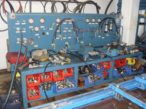
“The Beast” We Use to Test All Repairs

Check out “The Beast”

hydraulic-hose-fittings-test-bench


Okay so it isn’t exactly a beast BUT it is a huge bench that allows us to test every aspect of any hydraulic component.

When you have us repair or rebuild any hydraulic component, it goes through rigorous testing on our hydraulic test stand.

We use the test stand for:

  • Pumps
  • Cylinders
  • Valves
  • Motors (spin test)


Craig Cook

WARNING: Hydraulic Injury

Today I just want to share an incident that is a reminder to us all NEVER to be complacent when working on or around hydraulic equipment.

The dangers are always present, as this story illustrates:
An operator was using a high-pressure hydraulic tool, when the hose ruptured at the ferrule. As a result, high-pressure fluid came into contact with the operator’s hand.
 A
On presenting an Emergency, the initial prognosis was “keep clean and rest”. By chance, a specialist doctor observed and intervened.
 A
The mineral oil had already started to “eat away” fatty tissues in the hand and was travelling up the arm. The injured person had five operations to cut away oil deposits and at one point faced the prospect of losing his arm.

To fully appreciate the damage that hydraulic fluid under pressure can cause, you need see this photo of the injury.

If you’re squeamish, BE WARNED – it is very graphic.

Click here to see injury!

So make sure you know the ‘beast’ you’re dealing with. Educate yourself. And if you ever have any doubts when working on hydraulic equipment, consult a qualified engineer or technician.

But above all else, NEVER be complacent around hydraulic equipment.
Craig Cook

Water in hydraulic fluid is a contaminant that can be just as damaging as hard particles and in some cases, more so.

Water in hydraulic fluid:

  • Depletes some additives and reacts with others   to form corrosive by-products which attack some metals.
  • Reduces lubricant film-strength, which leaves critical surfaces vulnerable to wear and corrosion.
  • Reduces filter ability and clogs filters.
  • Reduces the oils ability to release air.
  • Increases the likelihood of cavitation occurring.
How much water is too much?

A number of factors need to be considered when selecting water contamination targets, including the type of hydraulic system and your reliability objectives for the equipment.

It’s always wise to control water contamination at the lowest levels that can reasonably be achieved, but certainly below the oil’s saturation point at operating temperature.

Water removal methods

Methods for removing free (unstable suspension) and emulsified (stable suspension) water include:

polymeric filters;

vacuum distillation; and

headspace dehumidification.
Polymeric filters – These look like conventional particulate filters, however the media is impregnated with a super-absorbent polymer.

Water causes the polymer to swell, which traps the water within the media. Polymeric filters are best suited for removing small volumes of water and/or maintaining water contamination within pre-determined limits.

Vacuum distillation – This technique employs a combination of heat and vacuum. At 25 inches of mercury, water boils at 133F (56C). This enables water to be removed at atemperature that does not damage the oil or its additives.
Headspace dehumidification – This method involves circulating and drying the air from the reservoir headspace. Water in the oil migrates to the dry air in the headspace and is eventually removed by the dehumidifier.

Vacuum distillation and headspace dehumidification also remove dissolved water.

Prevention is better than cure
 
Like all other forms of contamination, preventing water ingress is ten times cheaper than removing it from the oil.

Craig Cook

Copyright © 2025. All Rights Reserved.