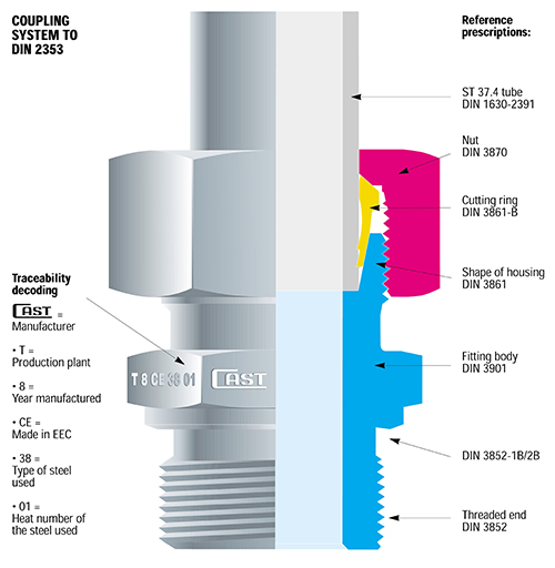
Coupling System to DIN 2353 Specifications
B3 Cutting Ring Theory of Operation
B4 Cutting Ring Theory of Operation
B3 and B4 General Instructions
B3 and B4 Assembly Instructions
B3 and B4 Utilization Standards

B3 Cutting Ring Theory of Operation
The cast fitting, manufactured according to ISO 8434-1/DIN 2353 norm is a mechanical fitting of deformable and cutting edge type ring with double stapling on the tube.
The ring helps fast assembly of removable tubes, avoids welding, tapping and flaring, thus assuring maximum simplicity of complex oleo-dynamic systems.
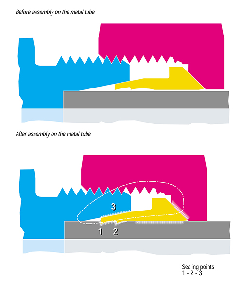
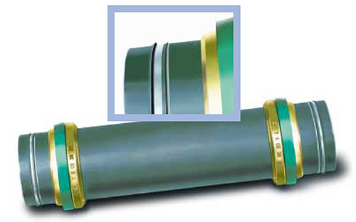
During tightening by the nut, the ring deforms according to the bore of the 24° cone of the fitting and bites into the steel tube, producing two deep cuts. The first of which is visible due to lifting of an outer edge on the diameter of the tube, allows the water tightness and anti-unthreading of the ring. The second groove (invisible) balances the forces on the whole ring, prevents vibration to reach the first groove and stops the stapling of the tube at a predetermined value.
Top of Page
B3 Technical Characteristics
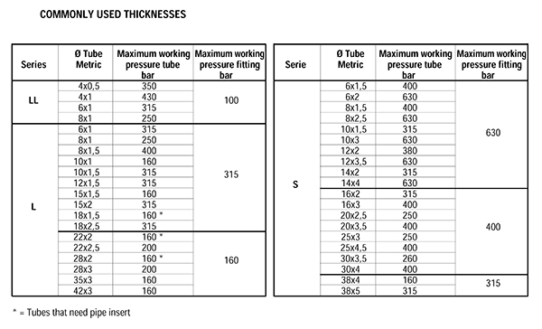
The Cast fitting assures a perfect seal, independently from the fluid used, provided that no corrosive fluids be employed and the nominal pressures be not trespassed. The DIN-2353 fittings are manufactured in three ranges to be chosen according to the required working conditions.
“LL” extra light range, suitable for low and medium working pressures and for circuits not subjected to water hammering up to 100 bar.
“L” light range, suitable for medium/high pressure plants however not over 315 bar.
“S” heavy range, for sever conditions, with high pressures, water hammering, high temperatures and a maximum pressure of 630 bar.
Vibrations according to the rules, don’t change the fitting’s performance that even at max values keeps its characteristics of the fitting with absolute reliability.
Top of Page
B4 Cutting Ring Theory of Operation
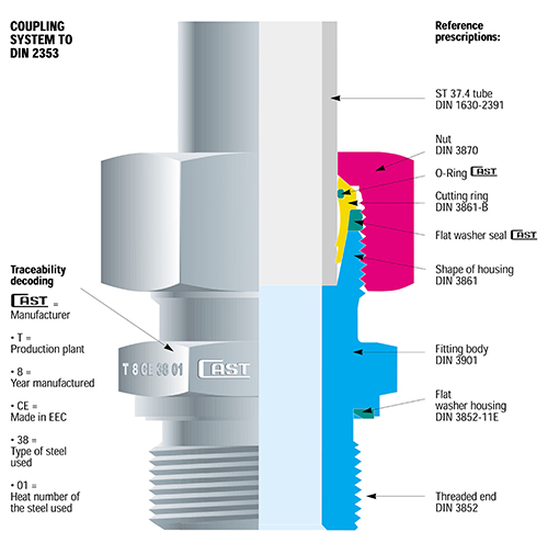
The “B4” is a highly innovative, deformable, double clinching, double edge ring with double elastomer seal that is assembled according to well known techniques and is perfectly interchangeable with all types of rings used on fittings with 24° cone complying with ISO 8434-1/DIN 2353 Fittings Standards.
The ring helps fast assembly of removable tubes, avoids welding, tapping and flaring, thus assuring maximum simplicity of complex oleo-dynamic systems.
During tightening by the nut, the ring deforms according to the bore of the 24° cone of the fitting and bites into the steel tube, producing two deep cuts, one of which is visible due to the lifting of an outer edge on the diameter of the tube.
Top of Page
B4 Technical Characteristics
The “B4” ring assures perfect tightness of the circuit regardless of the fluid used provided that corrosive fluids are avoided and the nominal pressures of the fittings are complied with. The fittings on which the “B4” rings are mounted are manufactured in two series that are used according to the operating conditions.
“L” light range series for applications characterized by medium high pressures, maximum 315 bar.
“S” heavy duty series for harsh applications characterized by high temperature and a maximum pressure of 630 bar.
When the fitting, ring, nut, tube system is assembled, the flat seal is compressed between the head of the cutting ring and the front of the fitting body. The mechanical pressure applied to the flat seal causes flexure towards the outside, with consequent increase in diameter. The deformation causes the compressed material of the seal to fill the turns of the thread of the nut free from the closing coupling with the fitting body, assuring locking of the nut and preventing any vibration-induced loosing of this.
Top of Page
B4 Originality and Features
Innovative Contents
For many years now, there has been an increasing imperative market demand for fluid system components able to guarantee three main factors: Safe Keying, Ease of Assembly and Leakage-Free Tightness. These elements, now considered essential for safety of the work environment, product liability and for the entire environmental protection system have promoted the development of the new “B4” ring as an effective response to all the above mentioned problems.
Originality of the Product
The most original aspect of the product is that the structure of the existing ring is has been used, inserting an o-ring in the inside part to obtain another seal on the tube used and a flat seal on the outer diameter to obtain 2 seals.
The main idea behind the development of the “B” was to design a new cutting ring able to go one step beyond the known techniques and to solve the problem of minor losses of tightness, leaks sweating and slipping of the system fastening nut.
With this new ring, double clinching of the steel tube is still possible and also, for obvious reasons of safety, visual inspection of correct coupling between the ring and the steel tube, also maintaining the current, perfectly functional system of assembly of the system of assembly that is now widely known to product users.
Tightness
“B4” solves the problem of absolute tightness in the following way:
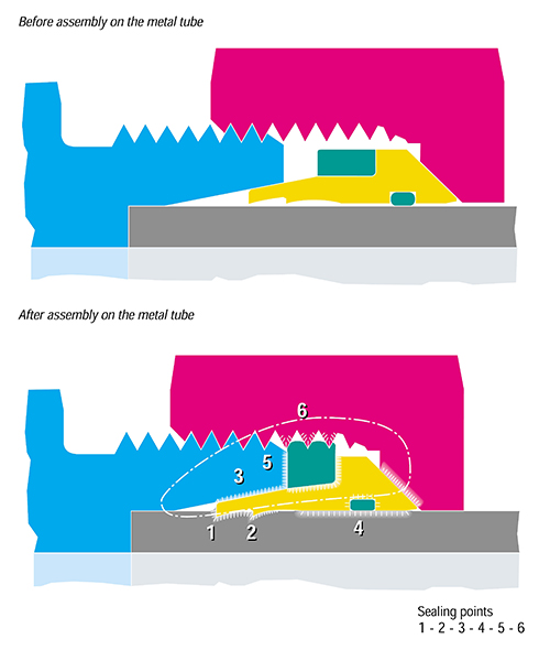
- On the outer diameter of the steel tube, with the double cut and with an o-ring placed inside the ring that provides a first seal with an elastomer material that didn’t exist before.
- In the 24° cone of the fitting body, with an increase in the metal on metal contact area and with flat seal, placed statically on the outer diameter of the cutting ring which, when compressed between the head of the ring and the front of the fitting body, provides a second seal with an elastomeric material that didn’t exist before.
- The the thread of the system fastening nut, with a flat seal. When this is compressed between the head of the ring and the front of the fitting body, it fills the thread of the nut that are not engaged in clinching the coupling system, thus providing a third seal with an elastomeric type material that didn’t exist before.
- Basically, the “B4” provides six points of seal of with three metal on metal and three by means of two soft elastomeric seals (the flat seal assures two points of seal) thus obtaining a product able to assure complete tightness without any possibility of leakages even in particularly harsh operating conditions.
Top of Page
B3 and B4 General Instructions
- Before starting the pre-assembly, make sure that the pierce of the machine and the hardened blocks are in perfect working order. Further inspections are necessary during the pre-assembly (every 30-50 tightenings). For this purpose CAST advise to use a control buffer 1000… pierce and block out of tolerance must be replaced.
- Over the whole tightening phase the tube must be in touch with the inner part of the body of the fitting. If this doesn’t happen, the ring will advance with the tube without indenting it, so the coupling would not be functional and it would be necessary to do the operation again. The tube must not turn with the nut during the tightening phase; the capability of the ring to rotate, once the pre-assembly is done, is not a deficiency but is a consequence of the right elasticity of the ring. Always check that the tube be correctly indented. If the indentation does not cover 70% of the ring front side then the indentation is not functional and must be done again. Indicated pressures are for steel tubes only.
- In case thin wall tubes are used, especially malleable tubes or tubes in Rilsan or similar, the assembly is possible, but a suitable reinforcement must be inserted into the end of the tube that is going to be tightened. Without the reinforcement it is not possible to operate with the above mentioned materials.
- Before assembling the pre-assembled tube to the equipment it is necessary to check that the tube and the fitting are aligned. The fitting should neither be used to correct a wrong alignment nor to be a support for the tube. Extremely long tubes or tubes undergoing high stress have absolutely to be fixed by using some support to avoid excessive vibrations that could cause damage to the system.
- The proper lubrication of components involved in the tightening is basic for good working. CAST advise to use mineral oils for carbon steel fittings and anti-seizing compound (Nickel basis) for Stainless Steel fittings.
- The fittings in this technical page may be used for fluidodynamic connections only.
- Is not allowed to mix carbon and stainless steel components.
Top of Page
B3 and B4 Assembly Instructions to DIN 3859-2 Specifications
- Before pre-assembly, make sure all the tools to be used are in perfect working order. Replace any inefficient tools.
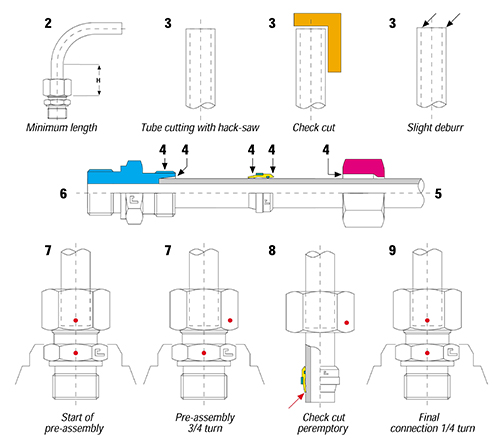
- The segment of tube to be pre-assembled must have a straight section at least twice the length of the nut (length H). Roundness must comply with DIN 2391.
- Cut the tube square by using an appropriate hack-saw (do not use roller type tube cutters) Check that the cut is properly made at 90°. Remove any internal and external burrs.
- Oil the 24° cone, the thread of the body, the cutting ring and the nut with suitable products.
- Fit the nut and the cutting ring on the tube as shown. The larger diameter of the cutting ring must face the nut.
- Insert the tube on the 24° cone until it comes into contact with the stop. Tighten the nut by hand until the cutting ring rest firmly on the nut. Then tighten the nut with a wrench until the cutting edge of the ring is in contact with the tube and prevents rotation of this.
- Holding the tube against the stop and making sure it does not rotate, tighten the nut by ¾ of a turn. This way, the cutting edge of the nut cuts into the outer part of the tube for the necessary depth and raises an edge in front of its cutting edge while the second cutting edge clinches the tube at the same time.
- Loosen the nut and check that there is a clearly raised edge all around the tube. The edge must cover 70% of the front of the cutting ring. This check is peremptory for the safety of all concerned! If the raised edge is not satisfactory, pre-assembly must be repeated.
- If pre-assembly has been carried out correctly, fit the tube on the machine, close with a wrench until a certain resistance is encountered and then tighten for a further ¼ turn with the wrench to wrench contrast.
- All the pre-assembly of stainless steel fittings must be performed with pre-assembly tool (blocks or machines).
The assembly of B3 and B4 rings must be done with the same procedures and tools. The two rings are completely interchangable with Italian and foreign products under the same norm. Assembly of the system may be repeated without damage to the parts involved.
Top of Page
Tightening Torques
Notes:
All the values reported in the above tightening tables are mere indications, and come from a series of practical test carried out in the technical laboratory of Volpiano (TO). These may vary according to the materials and of the tolerances of the employed components.
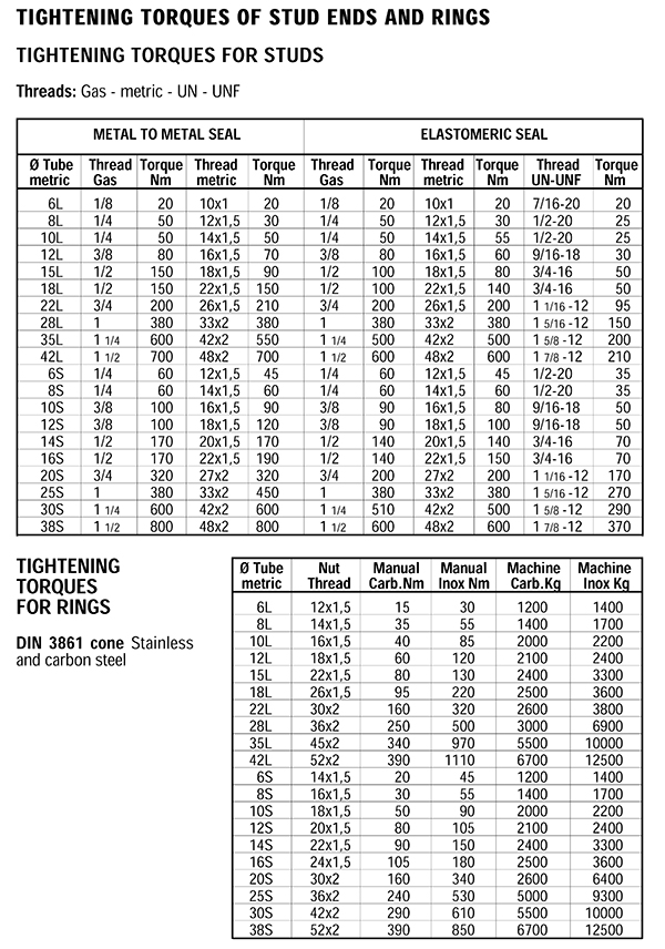
All the values that are express in Newton Meters (Nm) for the tightening torques of the stud threads represent the torquing moment necessary to have the correct blocking of the thread itself so to obtain a perfect sealing joint.
All the values express in Newton Meters (Nm) for the tightening torques on the cone DIN 3861 threads represent the torquing moment necessary to have the correct incision of the pre-assembly of the tube, lifting the required 70% of the front edge of the cutting ring. All values expressed in Kilograms (Kg) for the linear push on the pre-assembly machine, represent the right strength necessary to have the correct incision of the pre-assembly lifting the required 70% of the front of the edge of the cutting ring.
Once done properly the pre-assembly abd checked that all the components are conforming to the requirements of the system, finish the assembly itself, first closing by wrench until you feel a certain resistance, and then by doing the last ¼ of a turn to close the fitting completely.
Top of Page
B3 and B4 Utilization Standards
Carbon Steel Fittings
- High quality tubes must be employed to assure correct use and related technical performance of carbon steel fittings. Us of tubes without aforementioned characteristics may seriously impair the efficiency of the fitting. CAST recommend use of the following tubes only: ST 37.4 steel seamless tubes complying with DIN 1630, inner and outer tolerances as per DIN 2391, maximum permissable hardness 75 HRB.
- All carbon steel tubes with a diameter of more than 10 mm must be pre-assembled using the specific pre-assembly machine. If this is not available, hardened blocks, to be clamped in vice for manual pre-assembly, must be used. Remember to oil the thread, nut and ring. If hardened pre-assembly blocks are not available, normal fittings obtained from bars can be used. The fitting must be replaced at each tightening. Duringpre-assembly, pay particular attention to parts such as reducing standpipes and nipples as these are made of raw materials characterized, therefore, by higher resistance compared with the cuts made on annealed tubes. These parts must always be pre-assembled on hardened 24° cones (for all diameters).
Stainless Steel Fittings
- High quality tubes must be employed to assure correct use and related technical performance of stainless steel fitting. Use of tubes without the aforementioned characteristics may seriously impair the efficiency of the fitting. CAST recommend use of the following tubes only: Cold Drawn Seamless Tube 1.4571 as per DIN 17458-2391 or ASTM A 269-81. The maximum permitted hardness, measured on the outer diameter of the tube, is 85 HRB. Electrically welded tubes may be used provided they comply with the mechanical tolerance of the aforementioned standards and related hardness.
- All stainless steel tubes must be pre-assembled using the specific pre-assembly machine. If this is not available, hardened blocks must be used for manual pre-assembly. In this case, make sure that the bench and vice in which the block is clamped are firmly fastened to prevent any possibility of movement caused by the twisting moment applied to the nut during the pre-assembly phase. Assembly or pre-assembly operationsdirectly on the fitting are not allowed.
Quality Assurance According to UNI ISO 9001
The Quality Assurance System complies with UNI EN ISO 9001, certificate (N°90/94) issued by the RINA certification authority recognized by IQNET at European level.
At the customer’s request, CAST Quality Service will issue certificates of origin for the materisals used to manufacture the products delivered.
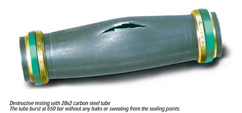
Testing
In addition to the normal dimensional checks carried out during machining, percentage inspections of the finished product, practical tightness and fatigue tests, coupling tests between various parts are also carried out on all CAST fittings.
At the customer’s request, CAST Product Test and Inspection Service issues the certificate of the tests carried out: dimensional and geometrical test, checking of static seal at low and high pressure, dynamic seal at high pressure (maximum operating pressure +33% as per DIN 3859). If required by the customer, tests can be carried out by various Third Party Authorities including: RINA-DVGW-Lloyd’s Register of Shipping-Det Norske Veritas-Germanischer Lloyd – American Bureau of Shipping (to be specified on the order).
Safety Factors
- B3 and B4 rings provides the right answer to safety problems so that absolute functional reliability between the ring, the steel tube and the fitting body is guaranteed by the double clinching and automatic locking of the cuts on the steel tube (assured by the particular shape of the ring).
- If, on one hand, the use of the “B4” improves the safety of the fastening, on the other hand a precise mechanical limitation is imposed on the cut in the tube, thus assuring correct functioning even in the case of excessive closing of the coupling. Obviously, the reliability of the CAST products is guaranteed only if the connections are made entirely with CAST products.
- CAST’s product range fully complies with the construction parameters of reference standards. Operating temperature is between -20°C and +100°C. The nominal operating pressures (bar) given in the catalog indicate the maximum permissible pressures (including pressure peaks). The safety factor is 4:1 and is intended with static load and with the temperature at the values indicated as per DIN 3861 (24° cone) for tube connection elastomeric seal. For stud couplings with conical or parallel threads with metal to metal seal the safety factor is 2.5:1.
Product Liability Presidential Decree 224-EC 85/374
CAST declines any responsibility in the case in which the user fails to comply strictly and entirely with the Rules for Use, Assembly Instructions and Operating Pressures Indicated. Failure to comply with these prescriptions may affect the functional safety of the products and result in voiding the user’s warranty rights.
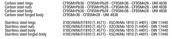
Steels Used on All Series
Allowed Working Temperatures
Carbon Mild Steel -20°C to +120°C, according to ISO 8434-1
Stainless Steel -60°C to +200°C, according to ISO 8434-1.
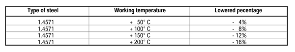
Pressure Rate Reduction
The allowed working pressure for stainless steel fittings manufactured with 1.4571 must be reduced according to the working registered temperatures according to ISO 8434-1. In case of multi-components systems all the parameters must be calculated on the weakest component used.
Gaskets
The gaskets used on fittings are normally manufactured in Vulkolan-Polisophrene, while thosed used on the stud ends are in NBR. All have a working temperature of -35°C to +100°C with a hardness of 85 ±5 shores. For higher temperatures Viton seals are suggested with working temperatures between -25°C to +200°C. All the items that are assembled with gaskets or seals of any kind must be handled according to DIN 7716 norm (requisites for the stocking of rubber products).
Seal on Threaded Ends
To obtain the maximum performance, the taper male thread is to be matched with the tapered female thread. The cylindrical male thread is to be matched with the cylindrical female thread. It is possible to match a taper thread with a cylindrical female thread, but this combination is technically valid only in pipings where low/medium performances are required and is never to be used where high pressures are applied. In case of matching of a cylindrical thread with relatively soft material, it is advisable to use the plain gasket type that guarantees a perfect seal even with a relatively low tightening torque.
Finish Treatment Carbon
All fittings are zinc plated according to UNI ISO 2081 and 4520. The plating thickness is 8 ÷ 12 microns and resistance in saline fog with standard salt concentration is 96 hours before the protective layer begins to wear off. Due to this treatment the parts may be used also in external exposure provided the the environment be not very aggressive. The cutting ring, after heat treatment to harden the surface, passivation treatment and ecological zinc-plating, follows a bath which facilitates the assembly.
Finish Treatment Inox
All the fittings are treated with steel spheres which eliminate all oxides and burrs due to the machining phase, without altering or damaging the product. After this, follows a bath to clean the product and take away the last impurities, if any. The piece at the end of the treatment looks very bright, very indicated for industrial applications where this type of steel is normally requested. On request different treatments can be performed. The cutting ring, after heat treatment to harden the surface, follows a bath which facilitates the assembly, protects the hardened film and improves the appearance of the ring.
Allowed Tubes on All Series
Carbon Steel
- For steel tubes in mild carbon steel CAST advise to use calibrated seamless cold drawn without welding tubes ST 37.4 as per DIN 1630.
- Maximum allowed hardness on the outside of the tube 75 HRB.
- The indicated pressures are to be intended on a constant pressure rate and with temperatures between -20°C and +120°C.
Stainless Steel
- For steel tubes in stainless steel CAST advise to use calibrated seamless cold drawn without welding tubes 1.4571 as per DIN 17458 or ASTM A 269.
- Maximum allowed hardness on the outside diameter of the tube 85 HRB.
- The indicated pressures on the below chart are intended on constant pressure rate and with temperature between -60°C and +200°C.
The not sufficient thickness of the tube walls, or the too low longitudinal resistance of the tubes (particularly mild soft steel) may create problems of cutting of the ring with the according losses of seals and the drastic decrease of the safety factor. While choosing the tube this aspect must be considered. Is good rule to pick tubes so that the internal flare (decreasing on the internal diameter) do not exceed 3/10 of a millimeter up to outside diameter of 16mm and 4/10 of a millimeter on higher diameters.
The thickness of the tube walls must be high enough to be able to sustain the maximum working pressure allowed a safety factor of 4:1, and with dimensions and tolerances according to DIN 2391/1.
Prescriptions to Comply with on All Series
- Use only CAST S.p.A. parts
- Apply completely the General Instructions
- Apply completely the Utilization Norms
- Apply completely the Assembly Instruction
- Apply integrally the Working Pressures indicated
- Respect the working temperature rates
- Respect the tightening values on DIN 3859
- Lubricate all the components with specific products
- All tubes must be properly pre-assembled or flared
- All stainless steel parts must be assembled on hardened tools
- Use only high quality stainless and carbon steel tubes
- Use strengthening ferrules on thin tubes walls
- Is not allowed to mix different materials
- Always check the correct alignment of the system
- Always check the correct incision on the tube
- In case of doubt always refer to the prudence concept
- Is not allowed, in any case, to use non conform tubes or fittings
Not following these prescription may alter greatly the functionally of the products causing problems to the system, and loss of all products guarantees.