Thread Identification
North American Connections
- National Pipe Thread (NPT)
- National Pipe Straight Mechanical (NPSM)
- JIC 37° Flare (SAE J514)
- SAE 45° Flare (SAE J512)
- SAE Straight Thread O-Ring (BOSS) (SAE J1926-1 & ISO 11296-1)
- Flareless Compression (SAE J514)
- O-Ring Face Seal (SAE J1453)
- Inverted Flare (SAE J512)
- Four Bolt Flange (SAE J518 & ISO 6162)
National Pipe Tapered (NPT)
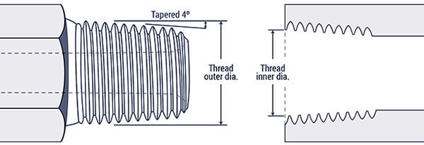
Sealing – The thread is tapered and the seal takes place by deformation of the threads. Thread sealant tape is recommended for a leak free connection.
| Inch Size | Dash Size | Nominal Thread | Male Thread OD (inch) | Female Thread ID (inch) |
| 1/8 | -02 | 1/8×27 | 13/32 (0.41) | 3/8 (0.38) |
| 1/4 | -04 | 1/4×18 | 17/32 (0.54) | 1/2 (0.49) |
| 3/8 | -06 | 3/8×18 | 11/16 (0.68) | 5/8 (0.63) |
| 1/2 | -08 | 1/2×14 | 27/32 (0.84) | 25/32 (0.77) |
| 3/4 | -12 | 3/4×14 | 1-1/16 (1.05) | 1 (0.98) |
| 1 | -16 | 1×11-1/2 | 1-5/16 (1.32) | 1-1/4 (1.24) |
| 1-1/4 | -20 | 1-1/4×11-1/2 | 1-21/32 (1.66) | 1-19/32 (1.58) |
| 1-1/2 | -24 | 1-1/2×11-1/2 | 1-29/32 (1.90) | 1-13/16 (1.82) |
| 2 | -32 | 2×11-1/2 | 2-3/8 (2.38) | 2-5/16 (2.30) |
Top of Page
National Pipe Straight Mechanical (NPSM)
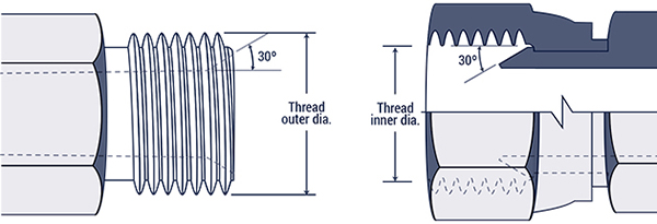
Sealing – The 30° seat of the female seals against the 30° chamfer on the male. The threads hold the connection mechanically. A NPT male with a 30° chamfer will also seal with a NPSM female.
| Inch Size | Dash Size | Nominal Thread | Male Thread OD (inch) | Female Thread ID (inch) |
| 1/8 | -02 | 1/8×27 | 13/32 (0.41) | 3/8 (0.38) |
| 1/4 | -04 | 1/4×18 | 17/32 (0.54) | 1/2 (0.49) |
| 3/8 | -06 | 3/8×18 | 11/16 (0.68) | 5/8 (0.63) |
| 1/2 | -08 | 1/2×14 | 27/32 (0.84) | 25/32 (0.77) |
| 3/4 | -12 | 3/4×14 | 1-1/16 (1.05) | 1 (0.98) |
| 1 | -16 | 1×11-1/2 | 1-5/16 (1.32) | 1-1/4 (1.24) |
| 1-1/4 | -20 | 1-1/4×11-1/2 | 1-21/32 (1.66) | 1-19/32 (1.58) |
| 1-1/2 | -24 | 1-1/2×11-1/2 | 1-29/32 (1.90) | 1-13/16 (1.82) |
| 2 | -32 | 2×11-1/2 | 2-3/8 (2.38) | 2-5/16 (2.30) |
Top of Page
JIC 37° Flare
SAE J514

Sealing – The seal is created by establishing a line of contact between the male 37° nose and the female 37° flare. The threads hold the connection mechanically.
| Inch Size | Dash Size | Nominal Thread | Male Thread OD (inch) | Female Thread ID (inch) |
| 1/8 | -02 | 5/16x 24 | 5/16 (0.31) | 9/32 (0.27) |
| 3/16 | -03 | 3/8×24 | 3/8 (0.38) | 11/32 (0.34) |
| 1/4 | -04 | 7/16×20 | 7/16 (0.44) | 13/32 (0.39) |
| 5/16 | -05 | 1/2×20 | 1/2 (0.50) | 15/32 (0.45) |
| 3/8 | -06 | 9/16×18 | 9/16 (0.56) | 17/32 (0.51) |
| 1/2 | -08 | 3/4×16 | 3/4 (0.75) | 11/16 (0.69) |
| 5/8 | -10 | 7/8×14 | 7/8 (0.88) | 13/16 (0.81) |
| 3/4 | -12 | 1-1/16×12 | 1-1/16 (1.06) | 1 (0.98) |
| 7/8 | -14 | 1-3/16×12 | 1-3/16 (1.19) | 1-1/8 (1.10) |
| 1 | -16 | 1-5/16×12 | 1-5/16 (1.31) | 1-1/4 (1.23) |
| 1-1/4 | -20 | 1-5/8×12 | 1-5/8 (1.63) | 1-9/16 (1.54) |
| 1-1/2 | -24 | 1-7/8×12 | 1-7/8 (1.88) | 1-13/16 (1.79) |
| 2 | -32 | 2-1/2×12 | 2-1/2 (2.50) | 2-7/16 (2.42) |
Top of Page
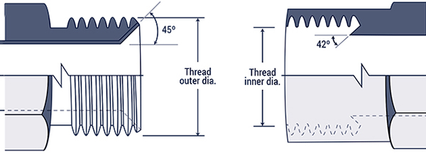
SAE 45° Flare
SAE J512
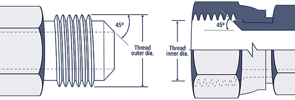
Sealing – Both the male and Female ends of this connection have 45° seats. The seal takes place between the male 45° nose and the female 45° flare. The threads hold the connection mechanically.
| Inch Size | Dash Size | Nominal Thread | Male Thread OD (inch) | Female Thread ID (inch) |
| 1/8 | -02 | 5/16x 24 | 5/16 (0.31) | 9/32 (0.27) |
| 3/16 | -03 | 3/8×24 | 3/8 (0.38) | 11/32 (0.34) |
| 1/4 | -04 | 7/16×20 | 6/16 (0.44) | 13/32 (0.39) |
| 5/16 | -05 | 1/2×20 | 1/2 (0.50) | 15/32 (0.45) |
| 3/8 | -06 | 5/8x 18 | 5/8 (0.63) | 9/16 (0.57) |
| 1/2 | -08 | 3/4×16 | 3/4 (0.75) | 11/16 (0.69) |
| 5/8 | -10 | 7/8×14 | 7/8 (0.88) | 13/16 (0.81) |
| 3/4 | -12 | 1-1/16×14 | 1-1/16 (1.06) | 1 (0.99) |
| 7/8 | -14 | 1-1/4×12 | 1-1/4 (1.19) | 1-5/32 (1.16) |
| 1 | -16 | 1-3/8×12 | 1-3/8 (1.31) | 1-9/32 (1.29) |
Top of Page
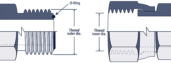
SAE Straight Tread O-Ring (BOSS)
SAE J1926-1 and ISO 11296-1
Conforms to MS16142, UN/UNF Threads
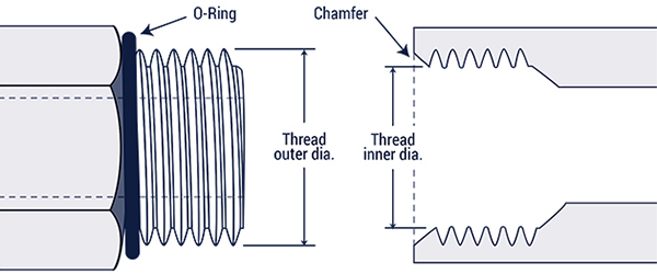
Sealing – The seal takes place by compressing the O-Ring into the chamfer. The threads hold the connection mechanically.
| Inch Size | Dash Size | Nominal Thread | Male Thread OD (inch) | Female Thread ID (inch) |
| 1/8 | -02 | 5/16x 24 | 5/16 (0.31) | 9/32 (0.27) |
| 3/16 | -03 | 3/8×24 | 3/8 (0.38) | 11/32 (0.34) |
| 1/4 | -04 | 7/16×20 | 7/16 (0.44) | 13/32 (0.39) |
| 5/16 | -05 | 1/2×20 | 1/2 (0.50) | 15/32 (0.45) |
| 3/8 | -06 | 9/16×18 | 9/16 (0.56) | 17/32 (0.51) |
| 1/2 | -08 | 3/4×16 | 3/4 (0.75) | 11/16 (0.69) |
| 5/8 | -10 | 7/8×14 | 7/8 (0.88) | 13/16 (0.81) |
| 3/4 | -12 | 1-1/16×12 | 1-1/16 (1.06) | 1 (0.98) |
| 7/8 | -14 | 1-3/16×12 | 1-3/16 (1.19) | 1-1/8 (1.10) |
| 1 | -16 | 1-5/16×12 | 1-5/16 (1.31) | 1-1/4 (1.23) |
| 1-1/4 | -20 | 1-5/8×12 | 1-5/8 (1.63) | 1-9/16 (1.54) |
| 1-1/2 | -24 | 1-7/8×12 | 1-7/8 (1.88) | 1-13/16 (1.79) |
| 2 | -32 | 2-1/2×12 | 2-1/2 (2.50) | 2-7/16 (2.42) |
Top of Page
Flareless Compression
SAE J514
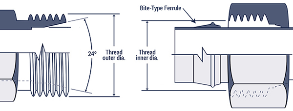
Sealing – The seal is made between the sleeve and the 24° seat. A seal is also made between the sleeve and the tubing. The threads hold the connection mechanically.
| Inch Size | Dash Size | Nominal Thread | Male Thread OD (inch) | Female Thread ID (inch) |
| 1/8 | -02 | 5/16x 24 | 5/16 (0.31) | 9/32 (0.27) |
| 3/16 | -03 | 3/8×24 | 3/8 (0.38) | 11/32 (0.34) |
| 1/4 | -04 | 7/16×20 | 7/16 (0.44) | 13/32 (0.39) |
| 5/16 | -05 | 1/2×20 | 1/2 (0.50) | 15/32 (0.45) |
| 3/8 | -06 | 9/16×18 | 9/16 (0.56) | 17/32 (0.51) |
| 1/2 | -08 | 3/4×16 | 3/4 (0.75) | 11/16 (0.69) |
| 5/8 | -10 | 7/8×14 | 7/8 (0.88) | 13/16 (0.81) |
| 3/4 | -12 | 1-1/16×12 | 1-1/16 (1.06) | 1 (0.98) |
| 7/8 | -14 | 1-3/16×12 | 1-3/16 (1.19) | 1-1/8 (1.10) |
| 1 | -16 | 1-5/16×12 | 1-5/16 (1.31) | 1-1/4 (1.23) |
| 1-1/4 | -20 | 1-5/8×12 | 1-5/8 (1.63) | 1-9/16 (1.54) |
| 1-1/2 | -24 | 1-7/8×12 | 1-7/8 (1.88) | 1-13/16 (1.79) |
| 2 | -32 | 2-1/2×12 | 2-1/2 (2.50) | 2-7/16 (2.42) |
Top of Page
Flat Face O-Ring (FFS)
SAE J1453
Sealing – The seal takes place by compressing the O-Ring onto the flat face of the female. The threads hold the connection mechanically.
| Inch Size | Dash Size | Nominal Thread | Male Thread OD (inch) | Female Thread ID (inch) |
| 1/4 | -04 | 9/16×18 | 9/16 (0.56) | 17/32 (0.51) |
| 3/8 | -06 | 11/16×16 | 11/16 (0.69) | 5/8 (0.63) |
| 1/2 | -08 | 13/16×16 | 13/16 (0.82) | 3/4 (0.75) |
| 5/8 | -10 | 1×14 | 1 (1.00) | 15/16 (0.93) |
| 3/4 | -12 | 1-3/16×12 | 1-3/16 (1.19) | 1-1/8 (1.11) |
| 1 | -16 | 1-7/16×12 | 1-7/16 (1.44) | 1-3/4 (1.36) |
| 1-1/4 | -20 | 1-11/16×12 | 1-11/16 (1.69) | 1-5/8 (1.61) |
| 1-1/2 | -24 | 2×12 | 2 (2.00) | 1-15/16 (1.92) |
Top of Page
Inverted Flare
SAE J512
Sealing – The seal takes place on the flared surfaces. The threads hold the connection mechanically.
| Inch Size | Dash Size | Nominal Thread | Male Thread OD (inch) | Female Thread ID (inch) |
| 1/8 | -02 | 5/16x 28 | 5/16 (0.32) | 9/32 (0.28) |
| 3/16 | -03 | 3/8×24 | 3/8 (0.38) | 11/32 (0.34) |
| 1/4 | -04 | 7/16×24 | 7/16 (0.44) | 13/32 (0.40) |
| 5/16 | -05 | 1/2×20 | 1/2 (0.50) | 15/32 (0.45) |
| 3/8 | -06 | 5/8×18 | 5/8 (0.63) | 9/16 (0.57) |
| 7/16 | -07 | 11/16×18 | 11/16 (0.69) | 5/8 (0.63) |
| 1/2 | -08 | 3/4×18 | 3/4 (0.75) | 23/32 (0.70) |
| 5/8 | -10 | 7/8×18 | 7/8 (0.88) | 13/16 (0.82) |
| 3/4 | -12 | 1-1/16×16 | 1-1/16 (1.06) | 1 (1.00) |
Top of Page
Four Bolt Flange
SAE J518 and ISO 6162
Interchangeable with DIN 20066 and JIS B 8363, except for the bolt sizes. All Caterpillar® Flange dimensions are identical to Code 62 dimensions on this chart. The difference is the flange thickness. All CAT flange sizes have a flange thickness of 0.56″.
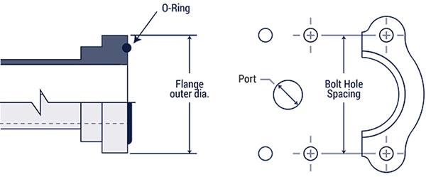
Sealing – An O-Ring, inserted into a ring groove in the flange head, seals on a smooth faced female port. It is held in place by two clamp halves and four bolts in a rectangular pattern.
| Port Size (inch) | Dash Size | Code 61 Bolt Spacing (inch) | Code 61 Flange Head Diameter (inch) | Code 62 Bolt Spacing (inch) | Code 62 Flange Head Diameter (inch) |
| 1/2 | -08 | 1-1/2 (1.50) | 1-3/16 (1.19) | 1-19/32 (1.59) | 1-1/4 (1.25) |
| 3/4 | -12 | 1-7/8 (1.88) | 1-1/2 (1.50) | 2 (2.00) | 1-5/8 (1.63) |
| 1 | -16 | 2-1/16 (2.06) | 1-3/4 (1.75) | 2-1/4 (2.25) | 1-7/8 (1.88) |
| 1-1/4 | -20 | 2-5/16 (2.31) | 2 (2.00) | 2-5/8 (2.63) | 2-1/8 (2.13) |
| 1-1/2 | -24 | 2-3/4 (2.75) | 2-3/8 (2.38) | 3-1/8 (3.13) | 2-1/2 (2.50) |
| 2 | -32 | 3-1/16 (3.06) | 2-13/32 (2.81) | 3-13/16 (3.81) | 3-1/8 (3.13) |
| 2-1/2 | -40 | 3-1/2 (3.50) | 3-5/16 (3.31) | – | – |
| 3 | -48 | 4-3/16 (4.19) | 4 (4.00) | – | – |
| 3-1/2 | -56 | 4-3/5 (4.75) | 4-1/2 (4.53) | – | – |
| 4 | -64 | 5-1/8 (5.12) | 5 (5.03) | – | – |
| Size | SAE | Flange Thickness (in) | O-Ring |
| -8 | Code 61 | 0.265 | 210 |
| -12 | Code 61 | 0.265 | 214 |
| -16 | Code 61 | 0.315 | 219 |
| -20 | Code 61 | 0.315 | 222 |
| -24 | Code 61 | 0.315 | 225 |
| -32 | Code 61 | 0.375 | 228 |
| -40 | Code 61 | 0.375 | 232 |
| -48 | Code 61 | 0.375 | 237 |
| -8 | Code 62 | 0.305 | 210 |
| -12 | Code 62 | 0.345 | 214 |
| -16 | Code 62 | 0.375 | 219 |
| -20 | Code 62 | 0.405 | 222 |
| -24 | Code 62 | 0.495 | 225 |
| -32 | Code 62 | 0.495 | 228 |
| CAT | CAT | (All Sizes) 0.560 | – |
Top of Page